Drone Gyro Stabilization, IMU And Flight Controllers Explained

The IMU, gyro stabilization, and flight controller technology are essential for a drone to fly perfectly stable. They provide navigational information to the flight controller, which makes drones easier and safer to fly. Gyro stabilization is surely one of the most needed components that is allowing the drone to fly super smooth even in strong winds and gusts.
These smooth flight capabilities allow us to film fantastic aerial footage of our beautiful planet. The latest drones use integrated gimbals, which also include inbuilt gyro stabilization technology giving the on-board camera or sensor on a drone the ability to shoot footage without vibrations. This allows us to capture perfect aerial films and photos.
The drones that have waypoint navigation, along with flight stabilization, have the ability to record and produce quality lidar imagery and 3D photogrammetry maps. Therefore, the gimbals are an essential technology for drones to have a stable image during the flight.
There are many different types of drones on the market today. Some have 3-axis gyro stabilization, some have 6-axis and others don’t use any at all. The type of drone you choose will depend on what features you’re looking for in your device.
For example, if you want to fly the drone indoors or take videos without too much shaking then a 3-axis is perfect for that! If you want to do flips and tricks or fly outside then 6-axis is much better suited for those needs.
In this article, you’ll find the difference between three-axis and six-axis stabilization systems as well as which top models have the best systems in place for autonomous flight modes. There are also informative videos throughout the article that will give you a better explanation.
Related Article: How do Drones Work and What is Drone Technology
Drone Gyro Stabilization Explained
The role of a gyroscope is to work instantly to the forces that are moving against the drone and to stabilize it. That’s why the gyroscope provides important navigational information to the central flight control systems.
The gyroscope technology is used to improve the flight capabilities of a drone. For example, the six-axis gimbal system feeds information about forces against the drone movement, such as gravity, wind, etc., and stabilizes the drone in real-time. The drone’s software, hardware and algorithms work in such way to improve the quadcopter’s flight capabilities such as hovering.
> Get Latest DJI Phantom 4 PRO Here <
A drone comes with an onboard computer that runs custom software and that is programmed specifically to operate drones so they can be flown remotely over long distances without interruption via 4G LTE networks – even if there’s no signal available where you’re at!
Here you can read, Drone Gimbals Explained.
Gyroscope Technology Within The IMU
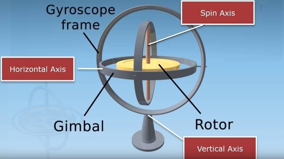
Today, many drones come with a gyroscope that is either integrated or encompassed within the IMU (Inertial Measurement Unit). The drone’s IMU along with satellite positioning (GPS and GLONASS) are components of its flight controller system too!
Working Principle of Drone IMU
IMU works by detecting the current rate of acceleration by using one or in some cases more accelerometers. They also detect changes in rotational attributes like pitch, roll, and yaw through gyroscopes. Some drones have an IMU with a magnetometer to assist calibration against orientation drift – though this isn’t always necessary.
When the drone is flying in the air, the onboard processor is continually calculating the drone’s precise position. For the quadcopter to calculate the current velocity, it integrates the acceleration in combination with the gravity. So the current position of a drone is then calculated by integrating the velocity.
For a drone to fly in any direction, the flight controller needs to collect the IMU data and then send that data to the quadcopter motor ESC system (electronic speed controllers). Then, the ESC sends the signal to the motors of the drone to level the correct thrust and speed that is required for a drone to fly.
If you want to know more about how a drone flies, read the interesting article Physics Behind How Drones Fly. Here you will learn all the things you need to know about drones.
It would be superfluous to list all the parts of which the drone consists in this article, but if you are interested, I wrote an article Drone Parts And Components Overview.
Drone Propulsion System
The drone’s propulsion system comprises the motor, ESC and propellers. These components are essential to flight safety for both novice and experienced pilots! The following components need to be included to have a full drone propulsion system;
- Motor Stator
- Rotor
- Cooling System
- Windings
- Bearings
- Propellers
- Electronic Speed Controllers
- ESC Updater
- Wiring
IMU Within The Flight Controller
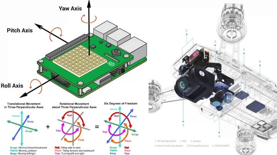
The flight controller is the brain of a drone. It comprises many parts, just like the gyroscope and IMU. By now we all know that the gyroscope is just one part of the IMU system, and the IMU is one of the essential parts of a quadcopter flight control system. Together, these components allows drones to fly steadily at all times- even in bad weather conditions!
You know that flight controllers are not just hardware. They include sophisticated software programs and mathematical algorithms, but all of these components must work seamlessly together for the drone to navigate with stability.
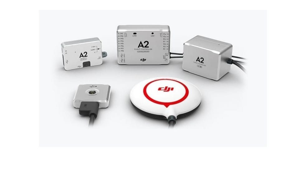
Here you can see the basic functions of the DJI A2 flight controller together with the IMU and gyroscope that are providing essential functions;
- Auto return to home
- Intelligent Orientation Control (IOC)
- Points Of Interest flight mode (POI)
- Fail protection
- Signal to the motor ESCs on thrust and direction
- Intelligent landing gear function
- High-precision satellite receiver
- Banked Turn Mode & Cruise Control Feature
Early Gyroscopes
John Serson invented the first gyroscope in 1743. The purpose of the first mechanical gyros was to detect changes in yaw, which helps keep an object stable and upright with respect to its rotational axis.
Some early mechanical models relied on spinning discs or mercury-filled gimbals that sensed acceleration forces from gravity as well as any rotation around their own axes that were caused by motion through space over time.
Modern alternatives are much more advanced than these earlier heavy power-consuming technologies because they can do so much more beyond just correcting for yaw – like measuring orientation, direction information about linear displacement (speed), angular velocity such as spin rate, etc., among many other things!
Gyro Stabilization In Drones
We know that drones are constantly being subjected to a number of different forces that are coming from all directions. The forces like wind affect the drone’s yaw, pitch, and roll making it hard for them to control their flight path. Therefore, the gyroscope was invented to control the drones during the flight.
Integrated gyroscopes that are installed in a quadcopter can almost instantly detect changes in position on your drone and stabilize it without you noticing as they re-adjust hundreds or even thousands of times every second, which will let your drone hover calmly in place so you’re able to concentrate more on getting perfect shots instead of worrying about if it’s going too fast.
3-Axis Vs 6-Axis Gyro Stabilization System
There are two main types of stabilization systems for quadcopters:
- 3-axis
- 6-axis
3-axis gyroscopes perfectly stabilize pitch and roll, tilt forward-backward and right-left. Thanks to this, the calibrated drone perfectly takes off and hovers in the air until the user sets the direction of movement in a certain direction. Once the control stick is level, the aircraft will return to a horizontal position and hover.
The 6-axis gyroscope system has sensors for pitch, roll, and yaw, and an accelerometer to calculate the required acceleration in different directions. In other words, the drone will be able to compensate for gusts of strong wind and almost instantly take a stable position.
The term “Six-axis gyro” refers to an integrated system that consists of a 3D accelerometer and 3D gyroscope (3 axis). In some cases, the accelerometer can be replaced with a 3D compass.
In addition, the 6-axis gyroscope automatically detects the drone’s incorrect position in the air and signals when the drone falls. This allows the pilot to align the sticks, increase the speed and stop the fall. This option saved many drones from damage.
Naturally, the control of a drone with a 6-axis system is easier, as it compensates for the lack of piloting experience and itself corrects many errors. Experienced pilots also prefer these gyroscopes because they make the drone more agile, nimble, and responsive.
> Get Latest DJI Mavic 3 Pro Here <
3D Accelerometer
The 3D accelerometer is a really cool piece of tech. It can measure the orientation of your drone relative to earth’s surface and it does this using some awesome technology! MEMS (Micro Electro-Mechanical Systems) are also behind gyroscopes, which means that engineers have an unlimited amount of possibilities when they design something with these tiny little things, such as drones.
Here, you can see a great video with a full explanation of how a 3D accelerometer works.
Advantages of Six-Axis Gyro Stabilization
A six-axis gyro can measure the amount of static and dynamic acceleration due to gravity. With these two measurements, we can determine how much a drone is tilted and which direction it moves in, respectively.
Since these drones are so stable, they’re perfect for beginners who want to learn to fly and get into drones. If you make any mistakes while piloting the drone with a 3-axis gyro then there will be if you are using a drone with a 6-axis gyro stabilization system.
Although 3-axis gyroscope stabilization can be helpful for some advanced maneuvers, a 6-axis gyro is buildup for advanced pilots. Beginners and pros alike will find this technology to their liking as the 6-axis stabilizing allows them to push drones further than ever before, allowing a better 3D imagery in an instant.
Accelerometer & Gyroscope Example
Here, you can find a great video showing how a quadcopter uses the gyroscope, 3-axis accelerometer, and a camera to stabilize itself in the air while flying.
The accelerometer detects that the drone has been thrown in the air and then it stabilize itself within a split second thanks to the help of gyroscope technology. Next, the distance sensor stabilizes the drone altitude so you’ll always know how far up or down your drone is. Finally, locking on with GPS enables the drone to fly where it needs to without crashing into some objects.
Flight Stability Best Practices
Remember that not even a 6-axis gyroscope technology will not help your drone if the drone’s hardware is not working properly. Therefore, if the propellers, motors, or shafts are not working properly, your drone can very easily crash.
Examining its parts is a great way to ensure your drone is always in tip-top shape before a flight. An important part of this process would be having spare components just in case something goes wrong or if the propellers become bent or cracked for any reason.
Keeping it clean will also help since dirt can affect how well everything works together on the inside as you fly around! If everything is looking good but your drone seems off balance when flying – bring it back right away.
My advice is to look at the drone after each flight and see if everything looks ok. This is the best way to make sure your drone last longer.
If you have a problem with your drone during the flight, be sure to calibrate the IMU on a flat surface first. Sometimes, it might need recalibrating more than once! Check your drone manufacturer’s website for any new firmware updates that may fix some of these issues too.
If you still experience problems after all this then there is probably something wrong with either your flight controller or IMU hardware.
Latest Drones With Best Flight Stabilization
Now we will list the most advanced and best drones that are available on the market and that come with gyro stabilization, GPS, IMU technology, and autonomous flight systems. These models also have safety features such as return to home (RTH) and home lock feature. So let’s start.
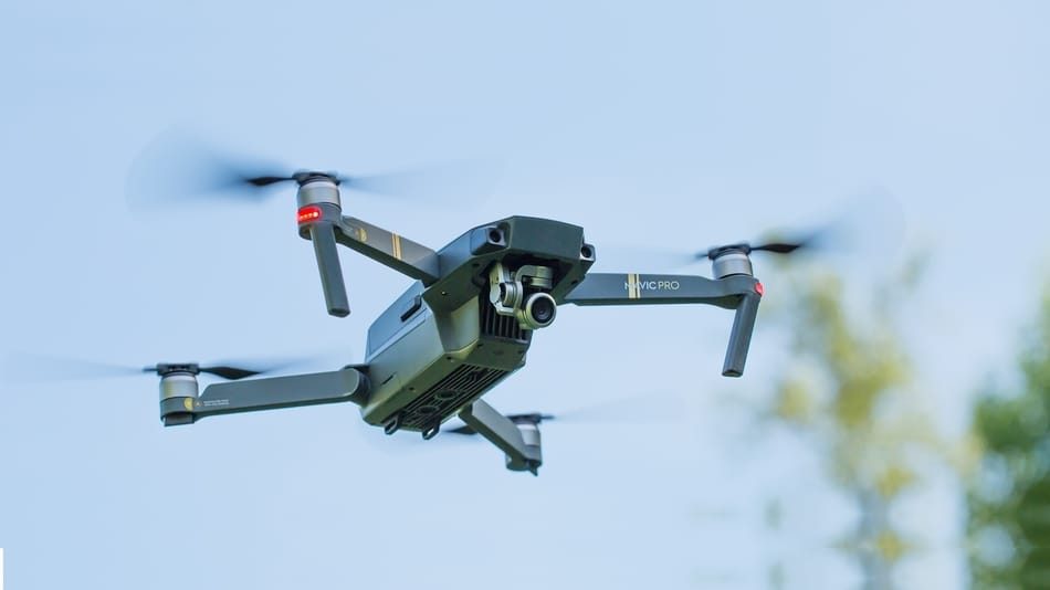
DJI Mavic 2 Pro & Mavic 2 Zoom – The new Mavic 2 Pro and Zoom quadcopters have the latest technology in navigation, flight control, and stabilization along with high-quality cameras. These models come equipped with Forward Vision Systems including Downward Infrared Sensing Systems that improve your navigational accuracy.
The Upwards and Longitudinal infrared sensing systems maintain stability as you fly higher up into the sky so you can get more breathtaking shots from a different angle without fear of getting too close or going over an obstacle! “The DJI-M2 has been designed for professionals who need to work quickly,” said Paul Pan at CES 2018 where he also unveiled some significant changes that are coming out.
The Forward, Backward and Downward Vision Systems comprise six camera sensors located on the nose, rear end and underside of the Mavic 2 quadcopter. The lateral Vision System consists of two cameras with one camera on each side that will help keep track in front or behind your drone during the flight.
And last but not least, this model have Upwards and Downwards Infrared Sensing Systems which consist of 3D infrared module that is located at top and bottom of the drone for scanning both ground-level obstacles as well as low-flying aircrafts so you are always safe when taking off!
The Mavic 2’s flight controller, IMU and Vision System are responsible for the camera work. The Flight Controller also controls how smoothly it can fly with precision accuracy indoors or outside where no GPS signal is available to help out!
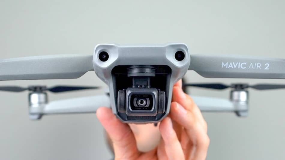
DJI Mavic Air – is a mini drone that was released in January 2018, and it employs the latest technology in Gyro IMU. The Mavic Air can be launch from your hand or from the ground, which makes him ideal for areas with long grasses or where you have snow because you won’t have to walk as far just to take off!
When the drone takes off from your hand, there’s no need for any complicated maneuvers – the drone will smoothly rise into air within seconds of takeoff. You also don’t have to worry that you will crash your drone. If things get too intense during the flight by using gestures (or via phone), tap on an obstacle icon at the bottom left corner of your screen and the drone will return to home.
The Mavic Air has an innovative facial recognition feature that uses sophisticated vision sensors and machine learning algorithms to detect and focus on the person or object in front of it. This model comes with an obstacle detection and collision avoidance features.
It can fly around obstacles or if the obstacle is too big, it will hover in front of it to avoid crashing. This incredible technology that comes with this drone has also terrific advanced equipment like Dronie, Circle Helix and Asteroid modes for you!
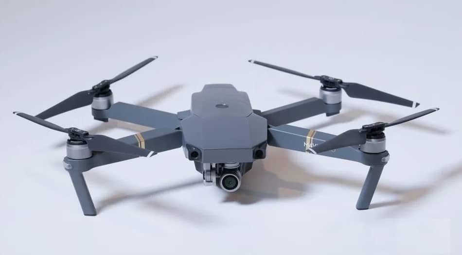
DJI Mavic Pro – drone comes with a foldable design for easy transportation. This model has “FlightAutonomy” technology, that provides the drone’s ability to fly and hover without interference from other objects in its environment.
This is possible by 5 cameras, 2 ultrasonic sensors, 24 powerful computing cores that are capable of processing 40 billion instructions per second (40 Gigahertz), dual-band satellite positioning which includes GPS and GLONASS technology, as well as redundant sensor systems that provide constant updates on flight status even if one system fails or loses connection with ground control stations during operation.
The camera lenses are fixed using an aluminum bracket ensuring optimum alignment while maintaining stability at all times. During the flight, the dual forward and downward vision sensors can easily measure the distance between obstacles by scanning and taking photos from built-in cameras and using that information to create a precise 3D map that will indicate where the obstacles are.
When it comes to dual forward and downward vision sensors, they require light to function properly. During the bright light, they can see up to 49 feet (15 m) in front. Every time you use Intelligent Flight Mode, this obstacle avoidance system is activated together with ActiveTrack modes, Terrain Follow, and TapFly modes.
DJI Phantom 4 Pro V2 – is a stunning quadcopter that has many features including a gyro-stabilized autonomous flight mode that includes collision avoidance and vision sensing. It can capture video in high definition and take pictures as well.
The DJI Phantom 4 Pro comes with an integrated gimbal that can capture stunning photos and videos in 4k. If you want to know more about this awesome model, you can watch this amazing DJI Phantom 4 Pro V2 video.
Yuneec Typhoon H – this unique multirotor quadcopter has everything you could ever need in a drone. It can shoot video at 4K and capture 12 megapixel still images with its 3-axis stabilized gimbal, while it also have the ability to fly around on autopilot modes like Orbit smoothly, Points of Interest (POI), Journey mode which follows a route for visuals such as cable cam shots or curved paths.
Curve Cable Cam Mode allows users to set up odd-shaped camera movements that follow an imaginary curve path all without using cables or any other attachments. A new innovative feature that comes with a drone is Follow Me / Watch me mode – this tracks your mobile device’s GPS location so it knows where you are.
Six Axis Gyro Stabilization Benefits
Unlike 3-axis gyro stabilization, drones that come with 6-axis gyroscope stabilization technology can benefit in the areas that are not only involved with aerial photography or filming.
1. Drone Acrobatics And Racing
There are a lot of people that enjoy using drones just for the pure pleasure of acrobatics and racing. Flipping a drone without crashing is difficult, but six-axis gyro stabilization can help you to have less stressful flight.
Drone racing relies heavily on fast flight control systems, so the pilot can avoid obstacles such as trees or buildings that appear in courses. Flying these high-speed racing drones takes skillful coordination between your eyesight and hands. In the following video you can see how it looks – FPV drone racing.
2. 3D Mapping And Photogrammetry
Pix4D and Aeryon Labs Inc partnered with PUC University of Rio de Janeiro to create the first 3-D map of Christ The Redeemer statue in Rio. It was a very difficult task to do. The changing weather, where the gusts of wind were up to 30 mph (50 km/h), complicated this project.
The leader for creating 3D maps and models by using photogrammetry software are Pix4D. But regardless of them, there are also other equally high-quality 3D mapping software companies.
What made this project possible was the flight control system, together with 6-axis gyro stabilization, waypoint navigation, and GPS. It has been confirmed that many other projects and sectors have a huge advantage from this technology.
This video will teach you how the MEMS accelerometer, magnetometer, and gyroscope work.
Why Calibration Is Important For Gyro Stabilization
A quadcopter’s flight is based on propellers’ acceleration and deceleration, which allow you to choose the direction of travel and hover in one place. The need of stabilization for these actions is carried out by the on-board computer that is based on information received from accelerometers and gyroscopes.
The panel controls the quadcopter, providing communication between the owner and the on-board computer. The quadcopter will easily execute all the indicated commands with the correct settings. If you launch the drone into flight without first checking, you may damage or lose the aircraft.
Conclusion
As you can see, gyro stabilization, IMU, and flight controller technology are one of the most important components in a drone. The three-axis or six-axis gyro stabilization technology allows for smooth flight capabilities that make flying drones much easier than ever before.
This means we can film fantastic aerial views without any worries about getting blown off course by strong winds or gusts. We hope you fully understand drone Gyro Stabilization, IMU And Flight Controllers and how they work.

